Showing posts with label Nondestructive. Show all posts

Abstract
Based on Biot’s theory of wave propagation in suspensions the utilization of the
ultrasound technique for the analysis of the setting and hardening of cementitious
materials became very popular over the last years. This is well documented in
numerous papers (for instance: SAYERS & DAHLIN [1993], BOUTIN & ARNAUD
[1995] or D’ANGELO ET AL. [1996]). The Institute of Construction Materials at the
University of Stuttgart - namely Prof. Dr.-Ing. H.-W. Reinhardt - started its
comprehensive research activities in the year of 1991. The most recent result of
this project is the development of an ultrasound device. It is shown in detail that
the method, applied to mortar materials, is able to document and analyze the
setting and hardening process continuously in a way that could not be achieved by
conventional techniques such as the vicat-needle test, the penetrometer test, the
slump test, or rheologic testing methods.

Introduction
Continuous research activities over the last decade are the basis for an ultrasound technique for measurements on time-dependent material properties that has been
developed at the Institute of Construction Materials, University of Stuttgart, under
the direction of Professor Dr.-Ing. H.-W. Reinhardt. This resulted in a measuring
device to investigate the hardening process of cementitious materials in terms of
material properties and quality control as well as in a patent specification which
was passed for registration under number 198 56 259.4 [1999] at the german
patent office (Deutsches Patent- und Markenamt, München). Numerous papers

[GROSSE & REINHARDT 1994; REINHARDT & GROSSE 1996; REINHARDT ET AL.
1996; REINHARDT ET AL. 1999; GROSSE & REINHARDT 1999a] describe the
evaluation of a suitable and applicable measuring technique.
Following the requirements of construction chemicals laboratories, a measuring
system was developed. In the following paragraphs the physical background as
well as some of the specifications are described. At the end some preliminary
results are shown, giving an impression of future applications.

Motivation and physical background
Modern concrete technology faces several challenges:
• there is a great demand by the design engineer for high-strength concrete,
high-performance concrete, fibre concrete;
• contractors are demanding for highly workable concrete, self-levelling
concrete, slip formed concrete, retarded mixes;
• there is less workmanship on the construction site available;
• there is increasing quality required for durable concrete structures in an
agressive environment.

The materials producers have a basket full of admixtures and additions which are
deemed to affect the fresh or the hardened state of concrete. The user is sometimes
inclined to combine various products in order to achieve the maximum success.
However, not all mixtures lead to the expected result.
An advanced process technology needs proper control by reliable and - as much
as possible - objective measurements. A possible solution is the ultrasound
technique, where amplitude-, velocity- and frequency-variations depending on the
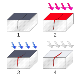
age of the mortar can be observed during the hardening process. The property of
cementitious materials are changing from a suspension to a solid during the
stiffening process caused by the hydratation of the cement-matrix. Biot’s theory
[BIOT 1956] describes the physical properties of this class of materials in an
adequate way, as was shown by own measurements [BOHNERT 1996]. Based on
this approach, using wave propagation theory, it became obvious that ultrasound
experiments measuring elastic waves in through-transmission are able to characterize the material during the stiffening process. Although the whole
waveform is representing the material properties, for quantitative analysis
techniques some parameters have to be extracted out of the signals recorded by a
measuring device. Parameters that are easy to determine are the velocity
(extracted by measuring the onset time of the signals knowing the travelpath of
the wave), the energy (calculating the integral sum of the wave amplitudes) and
the frequency content (using Fast-Fourier-Transform techniques). One has to keep
in mind that there are, of cause, also several other parameters that can be used.
Even though one single wave parameter could be sufficient to characterize the
material, the reliability of the method in increased by evaluating more than one.
In the following the application of the method in a certain field of interest is
shown.
Specifications for mortar measurements
The ultrasonic testing device freshmor 1 was developed at the University of
Stuttgart, Institute of Construction Materials. It enables the observation of the
setting and hardening process of mortar by means of ultrasonic throughtransmission.
Ultrasonic velocity and transmitted energy are the parameters that
are evaluated. The testing device, shown in figure 1, consists of a personal
computer with an A-D-conversion card, an ultrasonic generator, a mould with an
ultrasonic emitter/transducer pair and cables and connectors.
Since mortar contains no aggregates, the size of the mould could be reduced
significantly compared to former measurements on concrete materials
[REINHARDT ET AL. 1999]. The advantages are a better handling of the mould, a
smaller amount of material lost during the measurement, as well as less waste
causing additional costs.
The shape of the mould was designed to meet the following specifications:
• Robustness (using the mould repeatedly in laboratories),
• easy handling and fast replacement of specimen material,
• suppression of interferring waves through the walls of the container,
• mounting for piezoelectric transducers with reproducable coupling to the
tested material.
Fig. 1: Set-up for the mortar experiments showing the mould (rubber foam and PMMA-walls) and
the transducers.
An emitter-receiver pair of broadband conical transducers were chosen, which are
sensitive in a frequency range of 20 to 300 kHz. The conical shape of the
transducers enables the possibility of point-to-point measurements.
The signals measured during the stiffening process are recorded by an A/Dconcersion
device consisting of a fast A/D-transientrecorder PC-card controlled
by an IBM-compatible PC. On the emitting side, the signals are produced by an
US-generator via the conical transducer in time intervalls defined by the user.
Apart from the hardware, a lot of efford was made to bring the software in a userfriendly
laboratory-suited state. The software consists of three parts including the
control and monitor software used during the data acquisition, the extraction of
wave parameters used for the material characterization and the data analysis
software.
A list of software features was widely discussed with our research partners:
• Data acquisition and parameter extraction during a routine test as well as a
step-by-step parameter extraction in certain special applications (unknown
products or product components),
• waveform acquisition and recording with adequate amplitude resolution,
• automatic onset time picking with the highest reliability,
• flexible measurement intervals according to different periods of interest for
different admixtures,
• automatic processing of the signals including velocity and energy evaluation
during and after the test,
• extraction of additional material relevant parameters such as initial and final
setting time of the mortar.
Under the auspices of Professor Dr.-Ing. H.-W. Reinhardt the authors worked
together to meet all requirements including hardware and software as described in
the following.
Experimental setup and first results
Not all steps of the development can be described in detail. It was an iterative
process of finding a suitable shape for the mould. The final container has two
walls of PMMA and a U-shaped rubber foam. According to the description in the
patent specification [1999].
Some effort had to be done to fulfill all requirements regarding the software. An
important feature was the implementation of a dynamic software amplifier, which
was realized to enhance the amplitude resolution. The ultrasound waves travelling
through the mortar are highly attenuated in the beginning right after mixing. The
signal in the hardenend state, is however several decades higher in amplitude.
This significant increase in amplitude is a problem when using a device with 12-
bit hardware amplitude resolution without a gain ranging method.
To determine automatically the onset times of the compressional waves and
therefore the velocities with highest reliability, a special picking algorithm must
be used. Well-known algorithms using the crossover of signals above a given
threshold are not applicable in this case, because, for the given data, they were
tested with errors of over 100 percent in relation to the onset times. We have
developed a software called FreshCon which uses a combined energy-frequency
approach solving this problem. The algorithm was very well tested in numerous
applications and gives reasonable results even if the signal-to-noise ratio is low.
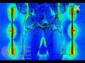
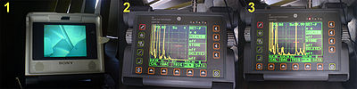
An example is shown in figure 2. A description of the software can be found in
GROSSE & REINHARDT [1999b].
Fig. 2: Example of an unfiltered US-signal in FreshCon using the semiautomatic picking mode.
For the final data analysis we used a comercially available software tool called
Origin (from MicroCal), which we have considerably modified with import
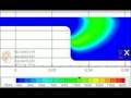
filters, templates, and macros. To give an impression of it‘s capabilities, figure 3
shows a typical sheet of data evaluation. The solid line is the calculated
compressional wave velocity depending on the age of mortar and the dotted line
shows the energy.
Fig. 3: Data analysis using the FreshMor-templates in the Origin-software. The straight lines at 2 h
39 min and 5 h 30 min give the values of the initial and final setting time of the material.
The operator is able to give a title for the sheet according to the tested material or
the date and time. In addition he may extract automatically the values of the initial
and final setting time of the mortar marked by two straight lines at certain ages.
Import and export of data as well as the print and documentation options are using
the latest MS-Windows standards including OLE-features for test documentation
with standard text processors.
First results
The first measurements have been conducted to test the reproducability of the data
curves. For these experiments, mortar mixtures consisting of a standard sand,
standard grain-size (∅ 0-2 mm) and water-to-cement ratio (no admixtures) have
been chosen. Three identical mixtures were tested – one after another. For the
mixing process itself we stood to the standard procedure for prisms according to
DIN EN 196-1, including a compaction time of two minutes. During this vibration
of approximately 0.7 mm horizontal amplitude, the mould was slowly be filled –
we learned that the devaporation of the material is important for proper and reliable results. Due to the time necessary for compaction and connection to the
US-device, the first data can be recorded after approximately 10 minutes. The
graphs in figure 4 demonstrate that the reproducability of the velocity and the
energy data are reasonable. Choosing standard settings for these test measurements,
the repetitive data acquisition interval was set to 10 minutes. For all
experiments described in this paper, the waveforms were averaged of five single
measurements, that is why every data point of the velocity and energy curves
represents five recordings. This procedure enhences the reproducability
condiderably. The variations at the end of the curves at later ages result from the
lower resolution according to shorter traveltimes in the hardenend material.

Fig. 4: Reproducibility test evaluate velocity and energy curves of three mortar mixtures of the same
kind.

Some preliminary results from experiments using the same mixture with different admixtures are shown as an example in figure 5. The curves represent the bandwith of tested materials showing the behaviour of the velocity as a function of the hardening age. Compared to the material without admixtures the velocity rises earlier when an accelerator is added to the mortar, and later when an air entrainer is added. The curve for the retarder starts at a higher velocity level due to the stabilizer containing the retarding additive. These test results should give an impression about the capabilities of this technique to investigate and classify a hardening material. Special mixtures as well as newly designed admixtures are able to be characterized in a new andpromising way.Fig. 5: Velocity (sligthly smoothed) versus age of mortar for 4 different mixtures.
Conclusions and acknowledgements
The ultrasonic device presented in this article is able to extract automatically
certain parameters of US waves recorded continously during the setting and
hardening of mortar materials. The resulting curves describe the material
behaviour and are related closely to the hydration process of the mortar. These
curves are linked to the elastic properties and give a comprehensive picture of the
stiffening process in a way that was not accessible before. Future applications in
industrial laboratories have to show, what kind of benefits are brought up by
recording the material properties of suspensions during hardening. Anyway, it is
obvious that this technique gives a clearer and more detailled insight than the
standard procedures that are measuring only one single parameter at certain
stiffness stages.
It is expected that the industrial use of this method will feedback in a further
improvement of the technique examining mortar materials. On the basis of these
experiences, the existing apparatus for concrete investigations will also be improved to enable measurements in-situ. It should be concluded, that apart from
this, the US-device will be modified for measurements on different other materials
such as polymers, ceramics or even starch.
The presented work is the result of a scientific project where many scientist and
students took part. The authors like to thank Jochen Fischer [1991], Nicole
Windisch [1996], Iris Kolb [1997] and Jens Bohnert [1996] for their
contributions. A very special thank-you is expressed by the authors to Prof. Dr.-
Ing. H.-W. Reinhardt for the initiation of this project, innumerable discussions
and his proficient and detailed help in all kind of problems. Without his efforts
and inertia, this research would not have been possible.

Requirements

  • First and last off inspection of production units (including in-process checks).
  • NDT testing (desirable).
  • CMM programmer or operator (advantageous).
  • IT skills (necessary).
  • A clear commitment to high quality standards and attention to detail.
  • Ability to promote quality policy within the business.
  • Manufacturing background with proven track record.
  • To develop new and existing methods of measurement wherever appropriate.
  • Maintain calibration schedule.
  • Support the production supervisor in meeting production schedule requirements.
  • To develop confidence in operators to discuss quality matters.
  • Teamwork skills, problem solving.
  • To promote continual improvements.
  • To train in other inspection functions to fully support the quality structure.
  • Improve the quality of information to identify root cause and corrective action.
  • Health & Safety awareness.
  • Ability to read engineering drawings.

Responsibilities including:

  • personal delivery of training courses and invigilation
  • management and leadership of a team, staff motivation and development
  • planning, management, resourcing and scheduling of programme delivery
  • development of updated high quality materials and methods of delivery
  • business development and marketing
  • pricing, budgeting and profitability
  • liaison with overseas subsidiaries on delivery and business development
  • strategic contribution to the Training & Exams management team.

* The oil and gas industry, with its numerous offshore platforms and extensive network of pipelines, is a significant user of NDT technologies necessary to assess the structural integrity of these installations. Underwater testing of welds in pielines is regularly performed for crack detection using visual, magnetic, electromagnetic, ultrasonic or radiographic techniques.

*Piping and structural welding.

*Welder qualification inspection for all process.Responsible for visual inspection, film interpretation, mechanical testing, nondestructive testing and reporting.
*Performed duties on projects throughout Worldwide for all types of testing and fabrication works.Inspecting welder training and qualification testing, process piping, storage tank, boiler & pressure vessel, structurl welding per international code/standard.

Assistant managerSenior welding inspector / NDT inspector NDT Level IIPersonnel for testing programs
*Performed NDT inspections, radiographic film interpretation and reporting at project sites.Supervised welder and inspector.
*Conducted welder testing and qualifications. Participated in marketing and preparation of proposals.

*Responsible for NDT operations and welder testing and training.
*Conducted welder and pipe filter qualification tests and welding procedure qualifications.Performed radiographic film interpretation, reporting and UT, MT, PT inspector and nondestructive testing.
*Assigned to marketing and preparation quotations.

*Manage all NDT operations and welding inspectors,
*Responsible for management of Welder Testing & Training programs, business development and marketing, budgeting and bidding.
*Provision of Welding Consultance & Designs (WPS, PQR,?WQT) and all procedure preparations.
*Conducting the WPS, PQR, WQT Qualification test for refinery, petrochemical plant, IPP, paper mill and etc..
*Review & approval of WPS, PQR, & WQT of various projects.
*Approval of WPS, PQR, WQT certificate of offshore works.
-Including negotiation with clients, preparation of NDT and inspections procedure and welding procedure as well as conducting the testing per client specifications and/or per international code standard.

Examinations

The South West School of NDT is an “Authorised Qualifying Body” for central certification examinations under the PCN scheme, administered by the British Institute of NDT. This is in satisfaction of EN 473 and ISO 9712. Additionally, the school routinely hosts examinations in satisfaction of employer-based schemes such as SNT-TC-IA, NAS 410 and EN4179.

Whilst central certification examinations are held at the school’s examination centre in Cardiff, NDT level 3 examination staff travel to national and international venues to administer employer-based examinations on behalf of a variety of clients.

Working in close collaboration with Ruane and T P O’Neill, the school can offer examinations in all major NDT disciplines and Industry sectors. It also specialised in arranging examinations in allied disciplines in such areas as Mechanical Testing, Heat Treatment, Acid Etch Inspection, Hardness and Conductivity, Anodic Flaw Detection, Composite Materials Inspection and Bond Testing. These are normally conducted under a structure similar to that for the mainstream methods and can be expended to include almost any technical discipline.

Inspection Technologies provides technology-driven inspection solutions (Non Destructive Testing [NDT] products and services) that deliver productivity, quality and safety. NDI design, manufacture and service ultrasonic, remote visual,radiographic (X-ray) and eddy current equipment and systems, and offer specialized solutions that will help you improve productivity in your applications in the aerospace, power generation, oil & gas, automotive or metals Industries.

Ultrasonic Testing
Flaw Detectors
Transducers
Thickness Gages
Ultrasonic Scanning Systems
Installed Sensors
Ultrasonic Instrumentations
Hardness Testing
Testing Machines and Integrated Systems


Remote Visual Inspection
Video Borescopes
Rigid Borescopes
Flexible Fiberscopes
Robotic Crawlers
Pan-Tilt-Zoom Cameras
Light Sources
Inspection Services
Equipment Rental


Radiography (X-ray)
Generators
Film Processors
Film
Computed Radiography
Digital Radiography
Analytical X-ray
Testing Machines and Integrated Systems


Eddy Current Testing
Instruments
Probes
Testing Machines and Integrated Systems


Others Products and Services
Software Solutions
Metrology
NDT Training
Equipment Services

CP-189 is a standart. This standart establishes the minimum requirements for the qualification and certification of NDT personnel.
This standart details the minimun trainingi education, and experience requirements for NDT personnel and provides criteria for documenting qualifications ant certification.
This standartrequires the employer to establish a peocedure for the cerfication of NDT personnel.
This standart requires that the employer incorporate any unique or additional requirements in the certification procedure.
Levels of Qualification;

  • trainee
  • NDT level I
  • NDT level II
  • NDT level III
  • NDT Instructor

SNT-TC-1A is a recommended practice..
It is recognized that the effectiveness of NDT aplications depends upon the capabilities of the personnel who are responsible for perform NDT. This recommended practice has been prepared to establish guidelines for the qualification and certification of NDT personnel whose specific jobs require appropriate knowledege of thecnical principles underlying the NDT they perform, witness, monitor or evaluate.
NDT Methods, Qualification and certification of NDT personnel in acorddance with this Recommended Practice is aplicable to each of the following methods:

  • Acoustic Emission Testing
  • Electromagnetic Testing
  • Laser Testing Methods
  • Leak Testing
  • Liquid Penetrant Testing
  • Magnetic Particle Testing
  • Neutron Radiographic Testing
  • Radiographic Testing
  • Thermal/Infrared Testing
  • Ultrasonic Testing
  • Vibration Analysis
  • Visual Testing

Signal propagation on a Printed Circuit Board


Magnetohydrodynamics Coupled Simulation of an arc in a Low...


Convergence of an iterative solver


Finite Volumes with Adaptive Meshes


Metamaterials - Split ring loaded waveguide


Hyperthermia Treatment


Current density inside the body induced by an electric blank


Nondestructive testing of materials


Induced current density inside the body


Thermal power denstity in the human head


Electric Field inside the Human Head.


Traveling Wave Tube


Electrons in a Pierce-Gun

1
2
From: TEMFTUD
3
4
5
6
From: TEMFTUD
7
8
9
10
11
12
From: TEMFTUD
13

No single NDT method will work for all flaw detection or measurement applications. Each of the methods has advantages and disadvantages when compared to other methods. The table below summarizes the scientific principles, common uses and the advantages and disadvantages for some of the most often used NDT methods.

Penetrant
Testing
Magnetic Particle Testing
Ultrasonic
Testing
Eddy Current
Testing
Radiographic
Testing
Scientific Principles
Penetrant solution is applied to the surface of a precleaned component. The liquid is pulled into surface-breaking defects by capillary action. Excess penetrant material is carefully cleaned from the surface. A developer is applied to pull the trapped penetrant back to the surface where it is spread out and forms an indication. The indication is much easier to see than the actual defect. A magnetic field is established in a component made from ferromagnetic material. The magnetic lines of force travel through the material, and exit and reenter the material at the poles. Defects such as crack or voids cannot support as much flux, and force some of the flux outside of the part. Magnetic particles distributed over the component will be attracted to areas of flux leakage and produce a visible indication. High frequency sound waves are sent into a material by use of a transducer. The sound waves travel through the material and are received by the same transducer or a second transducer. The amount of energy transmitted or received and the time the energy is received are analyzed to determine the presence of flaws. Changes in material thickness, and changes in material properties can also be measured. Alternating electrical current is passed through a coil producing a magnetic field. When the coil is placed near a conductive material, the changing magnetic field induces current flow in the material. These currents travel in closed loops and are called eddy currents. Eddy currents produce their own magnetic field that can be measured and used to find flaws and characterize conductivity, permeability, and dimensional features. X-rays are used to produce images of objects using film or other detector that is sensitive to radiation. The test object is placed between the radiation source and detector. The thickness and the density of the material that X-rays must penetrate affects the amount of radiation reaching the detector. This variation in radiation produces an image on the detector that often shows internal features of the test object.
Main Uses
Used to locate cracks, porosity, and other defects that break the surface of a material and have enough volume to trap and hold the penetrant material. Liquid penetrant testing is used to inspect large areas very efficiently and will work on most nonporous materials. Used to inspect ferromagnetic materials (those that can be magnetized) for defects that result in a transition in the magnetic permeability of a material. Magnetic particle inspection can detect surface and near surface defects. Used to locate surface and subsurface defects in many materials including metals, plastics, and wood. Ultrasonic inspection is also used to measure the thickness of materials and otherwise characterize properties of material based on sound velocity and attenuation measurements. Used to detect surface and near-surface flaws in conductive materials, such as the metals. Eddy current inspection is also used to sort materials based on electrical conductivity and magnetic permeability, and measures the thickness of thin sheets of metal and nonconductive coatings such as paint. Used to inspect almost any material for surface and subsurface defects. X-rays can also be used to locates and measures internal features, confirm the location of hidden parts in an assembly, and to measure thickness of materials.
Main Advantages

Large surface areas or large volumes of parts/materials can be inspected rapidly and at low cost.

Parts with complex geometry are routinely inspected.

Indications are produced directly on surface of the part providing a visual image of the discontinuity.

Equipment investment is minimal.

Large surface areas of complex parts can be inspected rapidly.

Can detect surface and subsurface flaws.

Surface preparation is less critical than it is in penetrant inspection.

Magnetic particle indications are produced directly on the surface of the part and form an image of the discontinuity.

Equipment costs are relatively low.

Depth of penetration for flaw detection or measurement is superior to other methods.

Only single sided access is required.

Provides distance information.

Minimum part preparation is required.

Method can be used for much more than just flaw detection.

Detects surface and near surface defects.

Test probe does not need to contact the part.

Method can be used for more than flaw detection.

Minimum part preparation is required.

Can be used to inspect virtually all materials.

Detects surface and subsurface defects.

Ability to inspect complex shapes and multi-layered structures without disassembly.

Minimum part preparation is required.

Disadvantages

Detects only surface breaking defects.

Surface preparation is critical as contaminants can mask defects.

Requires a relatively smooth and nonporous surface.

Post cleaning is necessary to remove chemicals.

Requires multiple operations under controlled conditions.

Chemical handling precautions are necessary (toxicity, fire, waste).

Only ferromagnetic materials can be inspected.

Proper alignment of magnetic field and defect is critical.

Large currents are needed for very large parts.

Requires relatively smooth surface.

Paint or other nonmagnetic coverings adversely affect sensitivity.

Demagnetization and post cleaning is usually necessary.

Surface must be accessible to probe and couplant.

Skill and training required is more extensive than other technique.

Surface finish and roughness can interfere with inspection.

Thin parts may be difficult to inspect.

Linear defects oriented parallel to the sound beam can go undetected.

Reference standards are often needed.

Only conductive materials can be inspected.

Ferromagnetic materials require special treatment to address magnetic permeability.

Depth of penetration is limited.

Flaws that lie parallel to the inspection probe coil winding direction can go undetected.

Skill and training required is more extensive than other techniques.

Surface finish and roughness may interfere.

Reference standards are needed for setup.

Extensive operator training and skill required.

Access to both sides of the structure is usually required.

Orientation of the radiation beam to non-volumetric defects is critical.

Field inspection of thick section can be time consuming.

Relatively expensive equipment investment is required.

Possible radiation hazard for personnel.

Penetrant
Testing
Magnetic Particle Testing
Ultrasonic
Testing
Eddy Current
Testing
Radiographic
Testing

NDT is divided into various methods of nondestructive testing, each based on a particular scientific principle. These methods may be further subdivided into various techniques. The various methods and techniques, due to their particular natures, may lend themselves especially well to certain applications and be of little or no value at all in other applications. Therefore choosing the right method and technique is an important part of the performance of NDT.


An example of Ultrasonic Testing (UT) on blade roots of a V2500 IAE aircraft engine.

An example of Ultrasonic Testing (UT) on blade roots of a V2500 IAE aircraft engine. Step 1: The UT probe is placed on the root of the blades to be inspected with the help of a special borescope tool (video probe). Step 2: Instrument settings are input. Step 3: The probe is scanned over the blade root. In this case, an indication (peak in the data) through the red line (or gate) indicates a good blade; an indication to the left of that range indicates a crack.Step 1: The UT probe is placed on the root of the blades to be inspected with the help of a special borescope tool (video probe).
Step 2: Instrument settings are input.
Step 3: The probe is scanned over the blade root. In this case, an indication (peak in the data) through the red line (or gate) indicates a good blade; an indication to the left of that range indicates a crack.
  • Liquid penetrant testing (PT or LPI)
1. Section of material with a surface-breaking crack that is not visible to the naked eye.2. Penetrant is applied to the surface.3. Excess penetrant is removed.4. Developer is applied, rendering the crack visible.

1. Section of material with a surface-breaking crack that is not visible to the naked eye.
2. Penetrant is applied to the surface.
3. Excess penetrant is removed.
4. Developer is applied, rendering the crack visible.

Liquid penetrant inspection is a widely applied and low-cost inspection method used to locate surface-breaking defects in all non-porous materials (metals, plastics, or ceramics). Penetrant may be applied to all non-ferrous materials, but for inspection of ferrous components magnetic particle inspection is preferred for its subsurface detection capability. LPI is used to detect casting and forging defects, cracks, and leaks in new products, and fatigue cracks on in-service components.

Principles

LPI is based upon capillary action, where low surface tension fluid penetrates into clean and dry surface-breaking discontinuities. Penetrant may be applied to the test component by dipping, spraying, or brushing. After adequate penetration time has been allowed, the excess penetrant is removed, and a developer is applied. The developer helps to draw penetrant out of the flaw where a visible indication becomes visible to the inspector. Inspection is performed under ultraviolet or white light, depending upon the type of dye used - fluorescent or nonfluorescent (visible).

Materials

Penetrants are classified into sensitivity levels. Visible penetrants are typically red in color, and represent the lowest sensitivity. Fluorescent penetrants contain two or more dyes that fluoresce when excited by ultraviolet (UV-A) radiation (also known as black light). Since FPI is performed in a darkened environment, and the excited dyes emit brilliant yellow-green light that contrasts strongly against the dark background, this material is more sensitive to small defects.

When selecting a sensitivity level one must consider many factors, including the environment under which the test will be performed, the surface finish of the specimen, and the size of defects sought. One must also assure that the test chemicals are compatible with the sample so that the examination will not cause permanent staining, or degradation. This technique can be quite portable, because in its simplest form the inspection requires only 3 aerosol spray cans, some paper towels, and adequate visible light. Stationary systems with dedicated application, wash, and development stations, are more costly and complicated, but result in better sensitivity and higher sample through-put.

Inspection Steps

Below are the main steps of Liquid Penetrant Inspection:

1. Pre-cleaning:

The test surface is cleaned to remove any dirt, paint, oil, grease or any loose scale that could either keep penetrant out of a defect, or cause irrelevant or false indications. Cleaning methods may include solvents, alkaline cleaning steps, vapor degreasing, or media blasting. The end goal of this step is a clean surface where any defects present are open to the surface, dry, and free of contamination.

2. Application of Penetrant:

The penetrant is then applied to the surface of the item being tested. The penetrant is allowed time to soak into any flaws (generally 10 to 30 minutes). The soak time mainly depends upon the material being testing and the size of flaws sought. As expected, smaller flaws require a longer penetration time. Due to their incompatible nature one must be careful not to apply visible red dye penetrant to a sample that may later be inspected with fluorescent penetrant.

3. Excess Penetrant Removal:

The excess penetrant is then removed from the surface. Removal method is controlled by the type of penetrant used. Water-washable, solvent-removable, lipophilic post-emulsifiable, or hydrophilic post-emulsifiable are the common choices. Emulsifiers represent the highest sensitivity level, and chemically interact with the oily penetrant to make it removable with a water spray. When using solvent remover and lint-free cloth it is important to not spray the solvent on the test surface directly, because this can the remove the penetrant from the flaws. This process must be performed under controlled conditions so that all penetrant on the surface is removed (background noise), but penetrant trapped in real defects remains in place.

4. Application of Developer:

After excess penetrant has been removed a white developer is applied to the sample. Several developer types are available, including: non-aqueous wet developer, dry powder, water suspendible, and water soluble. Choice of developer is governed by penetrant compatibility (one can't use water-soluble or suspedible developer with water-washable penetrant), and by inspection conditions. When using non-aqueous wet developer (NAWD) or dry powder the sample must be dried prior to application, while soluble and suspendible developers are applied with the part still wet from the previous step. NAWD is commercially available in aerosol spray cans, and may employ acetone, isopropyl alcohol, or a propellant that is a combination of the two. Developer should form a thin, even coating on the surface.

The developer draws penetrant from defects out onto the surface to form a visible indication, a process similar to the action of blotting paper. Any colored stains indicate the positions and types of defects on the surface under inspection.

5. Inspection:

The inspector will use visible light with adequate intensity (100 foot-candles is typical) for visible dye penetrant. Ultraviolet (UV-A) radiation of adequate intensity (1,000 micro-watts per centimeter squared is common), along with low ambient light levels (less than 2 foot-candles) for fluorescent penetrant examinations. Inspection of the test surface should take place after a 10 minute development time. This time delay allows the blotting action to occur. The inspector may observe the sample for indication formation when using visible dye, but this should not be done when using fluorescent penetrant. Also of concern, if one waits too long after development the indications may "bleed out" such that interpretation is hindered.

6. Post Cleaning:

The test surface is often cleaned after inspection and recording of defects (if found), especially if post-inspection coating processes are scheduled.

Features

  • The flaws are more visible, because:
    • The defect indication has a high visual contrast (e.g. red dye against a white developer background, or a bright fluorescent indication against a dark background).
    • The developer draws the penetrant out of the flaw over a wider area than the real flaw, so it looks wider.
  • Limited training is required for the operator — although experience is quite valuable.
  • Low testing costs.
  • Proper cleaning is necessary to assure that surface contaminants have been removed and any defects present are clean and dry. Some cleaning methods have been shown to be detrimental to test sensitivity, so acid etching to remove metal smearing and re-open the defect may be necessary.
  • Penetrant dyes stain cloth, skin and other porous surfaces brought into contact. One should verify compatibility on the test material, especially when considering the testing of plastic components.
  • Further information on inspection steps may be found in industry standards (e.g. the American Welding Society, American Society for Testing and Materials, the British Standards Institute, and the Society for Automotive Engineers).
  • Radiographic testing (RT)

Radiographic Testing (RT), or industrial radiography, is a nondestructive testing (NDT) method of inspecting materials for hidden flaws by using the ability of short wavelength electromagnetic radiation (high energy photons) to penetrate various materials.

Either an X-ray machine or a radioactive source (Ir-192, Co-60, or in rare cases Cs-137) can be used as a source of photons. Neutron radiographic testing (NR) is a variant of radiographic testing which uses neutrons instead of photons to penetrate materials. This can see very different things from X-rays, because neutrons can pass with ease through lead and steel but are stopped by plastics, water and oils.

Since the amount of radiation emerging from the opposite side of the material can be detected and measured, variations in this amount (or intensity) of radiation are used to determine thickness or composition of material. Penetrating radiations are those restricted to that part of the electromagnetic spectrum of wavelength less than about 10 nanometres.

Inspection of welds

The beam of radiation must be directed to the middle of the section under examination and must be normal to the material surface at that point, except in special techniques where known defects are best revealed by a different alignment of the beam. The length of weld under examination for each exposure shall be such that the thickness of the material at the diagnostic extremities, measured in the direction of the incident beam, does not exceed the actual thickness at that point by more than 6%. The specimen to be inspected is placed between the source of radiation and the detecting device, usually the film in a light tight holder or cassette, and the radiation is allowed to penetrate the part for the required length of time to be adequately recorded.

The result is a two-dimensional projection of the part onto the film, producing a latent image of varying densities according to the amount of radiation reaching each area. It is known as a radiograph, as distinct from a photograph produced by light. Because film is cumulative in its response (the exposure increasing as it absorbs more radiation), relatively weak radiation can be detected by prolonging the exposure until the film can record an image that will be visible after development. The radiograph is examined as a negative, without printing as a positive as in photography. This is because, in printing, some of the detail is always lost and no useful purpose is served.

Before commencing a radiographic examination, it is always advisable to examine the component with one's own eyes, to eliminate any possible external defects. If the surface of a weld is too irregular, it may be desirable to grind it to obtain a smooth finish, but this is likely to be limited to those cases in which the surface irregularities (which will be visible on the radiograph) may make detecting internal defects difficult.

After this visual examination, the operator will have a clear idea of the possibilities of access to the two faces of the weld, which is important both for the setting up of the equipment and for the choice of the most appropriate technique.

Defects such as delaminations and planar cracks are difficult to detect using radiography, which is why penetrants are often used to enhance the contrast in the detection of such defects. Penetrants used include silver nitrate, zinc iodide, chloroform and diiodomethane. Choice of the penetrant is determined by the ease with which it can penetrate the cracks and also with which it can be removed. Diiodomethane has the advantages of high opacity, ease of penetration, and ease of removal because it evaporates relatively quickly. However, it can cause skin burns.

  • Ultrasonic testing (UT)

In ultrasonic testing, very short ultrasonic pulse-waves with center frequencies ranging from 0.1-15 MHz and occasionally up to 50 MHz are launched into materials to detect internal flaws or to characterize materials. It is also commonly used to determine the thickness of the test object - monitoring pipework corrosion being a good example.

Ultrasonic Inspection is often performed on steel and other metals and alloys, though it can be used on concrete and other materials such as composites. It is a form of non-destructive testing used in many industries including aerospace, automotive and other transportation sectors.

How it works

In ultrasonic testing, a transducer connected to a diagnostic machine is passed over the object being inspected. In reflection (or pulse-echo) mode, the transducer sends pulsed waves through a couplant (such as water or oil) on the surface of the object, and receives the "sound" reflected back to the device. Reflected ultrasound comes from an interface - such as the back wall of the object or from an imperfection. The screen on the calibrated diagnostic machine displays these results in the form of a signal with an amplitude representing the intensity of the reflection and the distance taken for the reflection to return to the transducer. In attenuation (or through-transmission) mode, a transmitter sends ultrasound through one surface, and a separate receiver detects the amount that has reached it on another surface after travelling through the medium. Imperfections or other conditions in the space between the transmitter and receiver reduce the amount of sound transmitted thus indicating their presence.

Non-destructive testing of a swing shaft showing spline cracking

Non-destructive testing of a swing shaft showing spline cracking

Advantages

  1. Superior penetrating power, which allows the detection of flaws deep in the part.
  2. High sensitivity, permitting the detection of extremely small flaws.
  3. Only one surface need to be accessible.
  4. Greater accuracy than other nondestructive methods in determining the depth of internal flaws and the thickness of parts with parallel surfaces.
  5. Some capability of estimating the size, orientation, shape and nature of defects.
  6. Nonhazardous to operations or to nearby personnel and has no effect on equipment and materials in the vicinity.
  7. Capable of portable or highly automated operation.

Disadvantages

  1. Manual operation requires careful attention by experienced technicians
  2. Extensive technical knowledge is required for the development of inspection procedures.
  3. Parts that are rough, irregular in shape, very small or thin, or not homogeneous are difficult to inspect.
  4. Surface must be prepared by cleaning and removing loose scale, paint, etc. (UT can often be used successfully through paint that is properly bonded to a surface.)
  5. Couplants are needed to provide effective transfer of ultrasonic wave energy between transducers and parts being inspected unless a non-contact technique is used. Non-contact techniques include Laser and Electro Magnetic Acoustic Transducers (EMAT).
  6. Inspected items must be water resistant, when using water based couplants that do not contain rust inhibitors.
  • Visual and optical testing (VT)
  • Electromagnetic testing (ET)
Electromagnetic Testing (ET), as a form of nondestructive testing, is the process of inducing electric currents or magnetic fields or both inside a test object and observing the electromagnetic response. If the test is set up properly, a defect inside the test object creates a measurable response.

The term "Electromagnetic Testing" is often intended to mean simply Eddy-Current Testing (ECT). However with an expanding number of electromagnetic and magnetic test methods, "Electromagnetic Testing" is more often used to mean the whole class of electromagnetic test methods, of which Eddy-Current Testing is just one.

  • Acoustic emission testing (AE)
Acoustic Emission (AE) is a naturally occurring phenomenon whereby external stimuli such as mechanical loading generate sources of elastic waves. AE occurs when a small surface displacement of a material is produced. This occurs due to stress waves generated when there is a rapid release of energy in a material, or on its surface. The wave generated by the source of the AE, or, of practical interest, in methods used to stimulate and capture AE in a controlled fashion for study and/or use in inspection, quality control, system feedback, process monitoring and others.

Acoustic emission testing is used as a type of nondestructive testing technology. It is in the ultrasonic regime, typically within the range between 100 kHz and 1 MHz (although this range is not absolute). Acoustic emissions can be monitored and detected in frequency ranges under 1 kHz and have been reported at frequencies up to 100 MHz. Rapid stress-releasing events generate a spectrum of stress waves starting at 0 Hz and typically falling off at several MHz, but one strength of the technique is that background noise, particularly airborne, falls off more quickly, so the signal-to-noise ratio reaches an optimum value around the conventional frequency range.

A commonly accepted definition for AE is a transient elastic waves within a material due to localized stress release. Hence, a source which generates one AE event is the phenomenon which releases elastic energy into the material, which then propagates as an elastic wave. AE events can also come quite rapidly when materials begin to fail, in which case AE activity rates are studied as opposed to individual events. AE events that are commonly studied include the extension of a fatigue crack, or fiber breakage in a composite material among material failure processes. AE is related to an irreversible release of energy, and can be generated from sources not involving material failure including friction, cavitation and impact.

Transducers are attached to the material to detect these waves. Most of these sensors are in the frequency range of 20 kHz to 650 kHz. Some geophysical studies with AE use much lower frequency sensors, while sensors in the MHz range are also available commercially.

AE tools do not actively produce waves (or "insonify") as in conventional ultrasonics. Rather, they passively detect emissions from acoustic sources.

AEs from within a material are monitored to locate and/or define their source event. AE is even more commonly used to correlate when activity occurred with the level of stimuli or length of time before something occurred, such as determining the onset of cracking, documenting the failure of a part during unattended monitoring or the level of reoccurrence of AE during multiple load cycles. The last method listed is the basis for many safety inspection methods utilizing AE. Parts inspected with AE can remain in service.

  • Infrared and thermal testing (IR)
  • Laser testing
  • Leak testing (LT)

General Introduction to NDT Presentation

Nondestructive testing is a career field that is relatively obscure in the minds of the general public. The name seems totally self-explanatory, but most NDT professionals can relate to the experience of trying to explain what nondestructive testing means to family members, friends and acquaintances. Most students when considering career options are completely unaware that NDT is a very exciting and rewarding career field.

To help remedy the situation, an "Introduction to Nondestructive Testing" presentation has been prepared. The presentation is intended to be used by NDT professionals when they have the opportunity to address middle and high school classes, professional societies, or any other group willing to listen. The presentation can be downloaded and modified to meet the specific needs of the presenter.

All rights are reserved by the authors but the material may be freely used by individuals and organizations for general educational purposes. The materials may not be sold commercially, or used in commercial products or services. The presentation was prepared using PowerPoint 2002, so please note that some of the animation features may not function properly when used with a earlier version of the program.

Nondestructive testing (NDT), also called nondestructive evaluation (NDE) and nondestructive inspection (NDI), is testing that does not destroy the test object. NDE is vital for constructing and maintaining all types of components and structures. To detect different defects such as cracking and corrosion, there are different methods of testing available, such as X-ray (where cracks show up on the film) and ultrasound (where cracks show up as an echo blip on the screen). This article is aimed mainly at industrial NDT, but many of the methods described here can be used to test the human body. In fact methods from the medical field have often been adapted for industrial use, as was the case with Phased array ultrasonics and Computed radiography.

While destructive testing usually provides a more reliable assessment of the state of the test object, destruction of the test object usually makes this type of test more costly to the test object's owner than nondestructive testing. Destructive testing is also inappropriate in many circumstances, such as forensic investigation. That there is a tradeoff between the cost of the test and its reliability favors a strategy in which most test objects are inspected nondestructively; destructive testing is performed on a sampling of test objects that is drawn randomly for the purpose of characterizing the testing reliability of the nondestructive test.